
Precision Deburring for Difficult-Alloy CNC Machined Parts
Burrs and sharp edges can turn a "good" CNC part into a rejected assembly: O-ring cuts, poor sealing, unpredictable torque, coating failures, and failed visual or safety checks.
At AXALLOY Precision (Shenzhen), we provide precision deburring as part of a controlled machining route for difficult-to-machine alloys—so your parts assemble consistently, pass inspection, and ship with the documentation your engineering, procurement, and quality teams need.
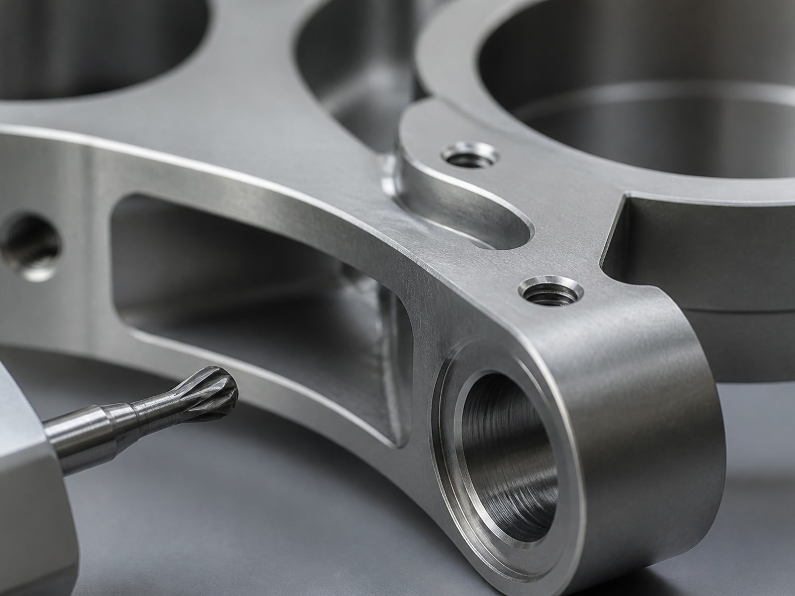
What You Get: Outcomes That Matter
If you have a drawing with edge-break notes, internal intersections, cross-holes, thin walls, or critical sealing features, send your RFQ and we'll propose a deburring method and inspection approach that fits your geometry, material, and risk level.
More Predictable Assembly and Fewer Hidden Failures
What you gain: smoother part-to-part fit, reduced risk of galling, and fewer leaks or damaged seals.
We plan deburring around functional interfaces—threads, bores, sealing faces, valve ports, manifolds, and precision pockets—so the edge condition matches how the part is actually used.
Lower Scrap Risk on High-Value Alloys
What you gain: fewer reworks and fewer parts scrapped late in the process.
Nickel alloys and titanium can be unforgiving: burrs work-harden, edges tear, and manual rework can change geometry. We select deburring steps that control edge break without sacrificing tolerances.
Cleaner Surfaces for Coating, Passivation, and Final Assembly
What you gain: reduced coating defects, better adhesion, and fewer contamination issues.
We support passivation, coating, cleaning, marking, and assembly support—so deburring doesn't become an isolated step that creates new quality problems.
Clear Quality Evidence for Engineering + Supplier Quality
What you gain: inspection outputs you can file and audit.
We can provide first article inspection, full dimensional reports, and certificates (material, heat treat, coating), with material and lot traceability when required.
Faster Iterations When a Burr Blocks Your Prototype Build
What you gain: quicker design validation and less downtime for your build team.
When your prototype schedule slips, your engineers often wait on "small" issues like edge condition, sharp internal corners, or burrs in cross-holes. Our prototype workflow (including deburring and inspection planning) helps you close fit/assembly feedback loops earlier, so you can lock designs and move to controlled repeat builds.
Where Precision Deburring Matters Most
Typical RFQ scenarios we handle daily:
- Cross-holes and intersecting bores — burrs that block flow or damage seals
- Thin walls (down to 0.5 mm) — where aggressive hand deburring can distort geometry
- Threads (down to M1.0; Swiss down to M0.8) — where entry burrs cause galling or false torque readings
- Critical sealing surfaces and valve features requiring consistent edge breaks
- EDM features needing cleanup without rounding sharp internal geometry
- High-mix repeat programs where edge condition must be consistent lot-to-lot
How We Control the Result
We don't assume "deburr all edges" means the same thing on every part. Before quoting, we review:
- Material behavior (Inconel vs. titanium vs. PH stainless)
- Geometry + accessibility (deep cavities, ribs, internal intersections)
- Tolerance stack and edge-break callouts
- Surface finish requirements and downstream coating/passivation
- Inspection strategy (critical edges, sampling level, reporting needs)
- Volume (prototype vs. repeat) for process stability and economy
If your drawing only says "Break all sharp edges," we can suggest practical edge-break ranges and identify where you should specify "no radius" or "controlled radius" to protect function.
Materials We Commonly Support
Nickel Alloys
- Inconel 718/625
- Hastelloy C-276/C-22
- Monel 400/K-500
- Haynes 188/230/282
- MP35N
Titanium
- Grade 2
- Grade 5
- Grade 23
Stainless Steels
- 316L
- 17-4 PH
- 15-5 PH
- Duplex 2205
- Super duplex 2507
Plus selected specialty metals: Nitinol, molybdenum, tungsten, copper-nickel.
Capability Parameters
Precision deburring quality depends on machining stability, repeatable setups, and inspection access. Below are reference capabilities that often define what edge conditions are feasible and repeatable.
General Machining & Finish Capabilities
| Parameter | Standard Capability |
|---|---|
| Production volume | 1–10,000+ parts |
| Minimum order quantity | 1 part |
| Standard dimensional tolerance | ±0.010 mm |
| Precision dimensional tolerance | ±0.005 mm |
| Position tolerance | Down to 0.010 mm |
| Flatness | Down to 0.005 mm |
| Concentricity | Down to 0.008 mm |
| Standard surface finish | Ra 1.6 μm |
| Precision machined finish | Ra 0.8 μm |
| Ground surface finish | Down to Ra 0.2 μm |
| Minimum wall thickness | 0.5 mm |
| Minimum hole diameter | Ø0.5 mm |
| Minimum thread size | M1.0 |
| Prototype lead time | 5–10 business days |
| Standard lead time | 10–20 business days |
| Expedited service | Available |
EDM + Grinding (Often Paired with Controlled Edge Requirements)
| Process | Key Capability Points |
|---|---|
| Wire EDM | Accuracy ±0.005 mm; finish Ra 0.8 μm; max taper ±30° |
| Sinker EDM | Finish Ra 0.4 μm; min internal corner radius R0.05 mm |
| Precision grinding | Tolerance ±0.002 mm; finish Ra 0.2 μm; roundness 0.002 mm |
Inspection & Documentation
| Item | Capability |
|---|---|
| CMM range | 700 × 1,000 × 600 mm |
| CMM accuracy | Up to 1.8 + L/300 μm |
| Optical measurement | ±0.002 mm |
| Surface roughness | Ra 0.05–40 μm |
| FAI / Full inspection | Available |
| Traceability | Material & lot traceability |
| Quality records | MTR/MTC, CoC, FAI report, ballooned drawing, dimensional report, coating/heat treat certs |
RFQ Checklist
To quote precision deburring correctly (and avoid later ECOs or disputes), include:
- 1 2D drawing (PDF) + 3D model (STEP/STP preferred)
- 2 Material grade (e.g., Inconel 718, Titanium Gr5, 17-4 PH)
- 3 Quantity (prototype and/or annual demand)
-
4
Edge requirements
- • Callouts like edge break, deburr notes, max radius, "no rounding" zones
- • Identify critical interfaces (seals, threads, mating faces, flow paths)
- 5 Surface finish requirements (Ra) and any coating/passivation/cleanliness needs
- 6 Inspection & documentation requirements (FAI, full report, traceability, certs)
- 7 Target ship date and delivery location
Supported file formats (up to 500 MB): STEP/STP, IGES/IGS, X_T/X_B, SLDPRT, SAT; drawings: PDF/DWG/DXF
When AXALLOY Is a Good Fit
Good Fit
Complex parts, difficult alloys, tight GD&T, high-value prototypes, low-volume or repeat builds, and projects transferred from an unreliable supplier—especially when you need documentation and predictable communication.
Not a Fit
Commodity parts purchased purely on the lowest unit price, incomplete requirements, or unauthorized reproduction.
Request an RFQ
We'll reply with a process-minded quote. Upload your drawing/model and tell us:
- Alloy + quantity
- Which edges are functional/critical
- Required inspection package
We'll respond with a quote and a proposed manufacturing route that includes a deburring approach aligned to your geometry, tolerance risk, and downstream processes.