
Precision CNC Machining Partner
Motion-Control Components | Precision CNC Machining
AXALLOY Precision is a Shenzhen-based CNC machining partner focused on high-value, complex parts and assemblies for motion-control systems. From prototype development to controlled low-volume and repeat production, we machine difficult alloys and deliver the process control, documentation and responsiveness that engineering, procurement and quality teams expect.
Core Focus
Precision interfaces, tight geometric tolerances, thin walls, critical surfaces and difficult holes/threads
Materials
Titanium, precipitation-hardening stainless steels, duplex/super duplex, nickel-based superalloys, cobalt alloys
Deliverables
Traceable materials, first article inspection, dimensional reports and project-specific quality records
What We Machine for Motion Control
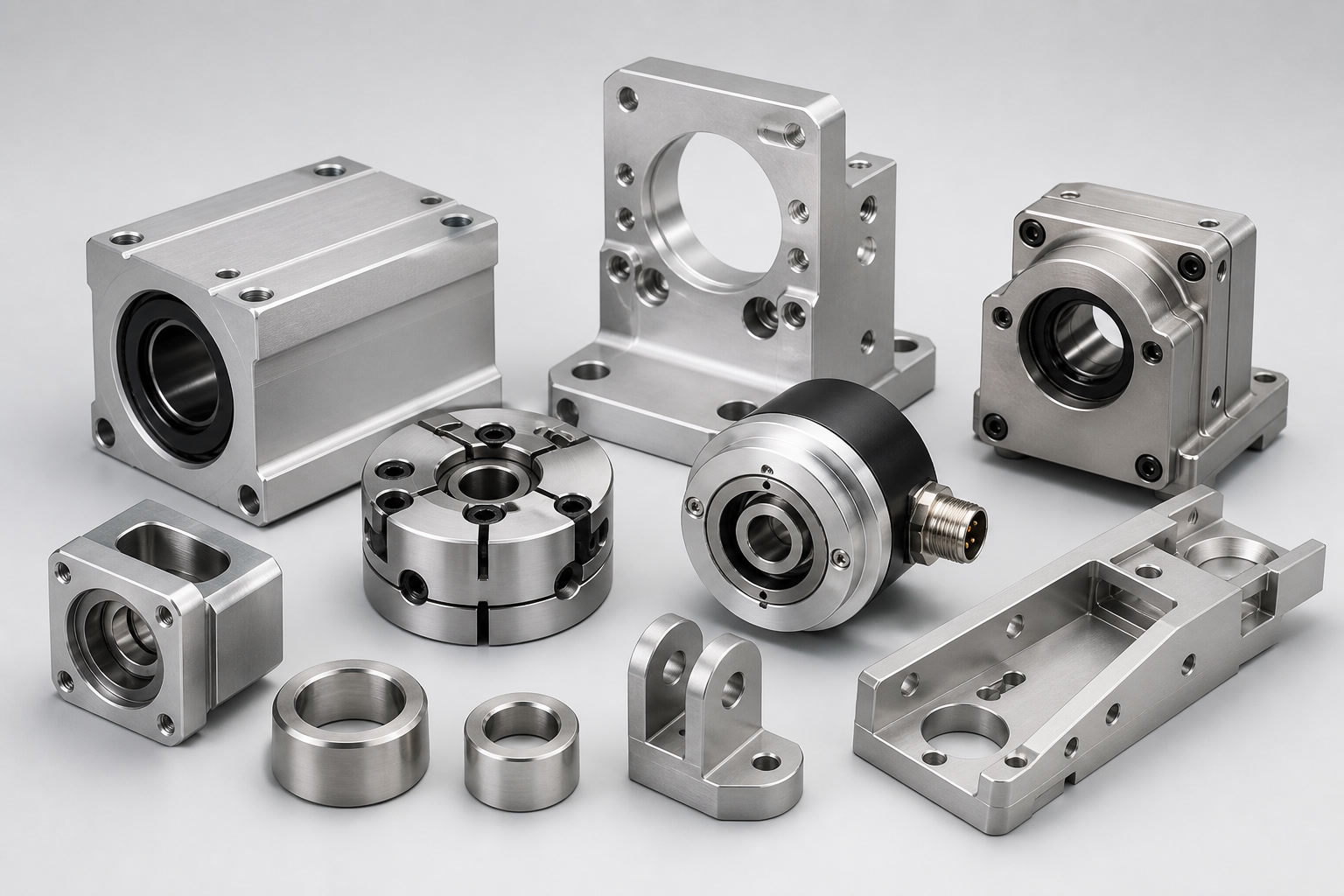
We produce precision components and subassemblies used in linear and rotary motion, robotics, semiconductor equipment, medical devices and precision automation.
Linear Motion
Bearing blocks, rail carriages, slide/way plates, ball-screw and nut housings, spacer plates, end caps, alignment keys
Rotary Motion
Shafts, spindles, hub/shaft couplings, encoder/servo motor mounts, gear carriers, pulleys and timing interfaces
Guidance and Positioning
Bearing seats and sleeves, bushings, cams, precision dowel interfaces, kinematic mounts, alignment brackets
Fluid-Power Motion
Valve bodies, manifolds, nozzles, fittings and precision threaded connectors
High-Stiffness Frames
Actuator flanges, interface plates, brackets, structural housings and lightweighted 5-axis milled components
Why AXALLOY for Motion-Control Components
We combine difficult-alloy expertise with precision process capability and rigorous documentation to deliver components that perform reliably in demanding motion-control applications.
Difficult-Alloy Expertise
- •17-4 PH, 15-5 PH, 316L, Duplex 2205, Super Duplex 2507 for strength and corrosion resistance
- •Titanium Grades 5/23 for high stiffness-to-weight and cleanroom/vacuum compatibility
- •Inconel 718/625 and Hastelloy for high-temperature, chemical or vacuum conditions
Process Capability for Precision Fits
- •5-axis milling for complex contours and controlled datum relationships
- •Mill-turn for coaxiality and feature-to-feature accuracy in a single setup
- •Precision grinding for bearing fits, sealing surfaces and low runout
- •EDM for sharp internal corners, thin ribs and narrow slots without burr propagation
Inspection and Documentation
- •FAI, ballooned drawings, full dimensional reports, surface roughness, hardness and special-process records
- •Material and lot traceability, CoC and export-ready packaging
Communication and Control
- •DFM/tolerance review, fixture planning, process development and transparent status updates
Tolerances and Surfaces We Routinely Support
These ranges support typical motion-control features such as bearing seats, linear guide interfaces, sealing surfaces, encoder mounts and precision datum planes.
Dimensional Tolerance
- ±0.005 mm standard
- ±0.002 mm ground features
Geometric Control
- Position: 0.010 mm
- Flatness: 0.005 mm
- Concentricity: 0.008 mm
- Roundness: 0.005 mm
- Angular: ±0.1°
Surface Finish
- Machined: Ra 0.8 μm
- Ground: Ra 0.2 μm
- EDM: Ra 0.8 μm
Feature Limits
- Thin walls: 0.5 mm
- Holes: Ø0.5 mm
- Threads: M1.0 / M0.8 Swiss
Capabilities Aligned to Motion-Control Demands
Our equipment and process range is sized to handle the precision, material and geometric challenges of motion-control components.
CNC Milling
3-, 4- and 5-axis; X 1,000 × Y 600 × Z 600 mm; up to 20,000 rpm; positioning accuracy ±0.005 mm; repeatability ±0.003 mm
CNC Turning
Ø500 × 1,000 mm; bar capacity Ø80 mm; roundness down to 0.005 mm
Mill-Turn
Up to 9 axes; live tooling up to 12,000 rpm; concentric features in one setup
Swiss Turning
Micro and slender parts up to Ø32 mm; length up to 300 mm
Precision Grinding
Surface, cylindrical, centerless; flatness down to 0.003 mm; roundness down to 0.002 mm; Ra 0.2 μm
EDM
Wire and sinker for sharp corners, thin ribs, deep cavities and hard materials
Special Processes
Heat treatment (e.g., 17-4 PH H1025/H1150), passivation, coating, deburring, marking, cleaning and assembly support
Engineering and DFM Guidance for Motion-Control Parts
We collaborate early to stabilize performance and cost while protecting critical function.
Datum Strategy and Stack-Up
- Define functional datums tied to the assembly path (e.g., bearing-seat axis to mounting face)
- Minimize datum transfers by grouping related features into single setups
Tolerance Allocation
- Reserve tight tolerances for functional surfaces (bearing bores, rail lands, dowel interfaces)
- Apply GD&T (position, runout, parallelism, perpendicularity, flatness) to control function, not non-critical profiles
Fits and Finishes
- Bearing seats: specify class of fit and roundness/cylindricity; we typically grind or finish-bore to final size
- Sliding ways: call out flatness/parallelism and Ra; confirm orientation of lay
- Sealing surfaces: define flatness and surface finish; avoid unnecessary surface treatments that affect seal friction
Feature Design
- Add thread reliefs and undercuts for full-thread engagement on hard alloys
- Use generous corner radii (≥ R0.5 where function allows); minimum internal corner radius R0.3 mm
- For thin walls (≥ 0.5 mm), add ribs or machining allowances for stress relief
Materials and Treatments
- 17-4 PH: specify condition (e.g., H1025) and dimensional strategy across heat treat and finish-grind stages
- Duplex/316L: consider passivation and galling mitigation for threads/fits
- Titanium/Nickel alloys: plan for lower MRR, stable fixturing, and potential post-machining stress relief
Cleanliness, Burr Control and Repeatability
- Specify critical edges to break vs. protect; define deburr/cleaning level for cleanroom or vacuum use
- Approve a stable process route via FAI; document special processes and gage strategy for repeat production
Quality, Inspection and Records
Metrology
- CMM: 700 × 1,000 × 600 mm; up to 1.8 + L/300 μm accuracy
- Optical measurement: ±0.002 mm; surface roughness Ra 0.05–40 μm
- Hardness: Rockwell, Brinell, Vickers; thread inspection via gauges/optics
- Temperature-controlled inspection room; calibrated equipment
Documentation
- Material test reports and mill certificates
- First article inspection (AS9102-style on request), ballooned drawings, full dimensional reports
- Heat treatment and coating certificates, surface roughness reports
- Material/lot traceability and project-specific quality records
- Inspection photos upon request
Programs, Volumes and Lead Times
Prototype
1–20 parts; typical lead time 5–10 business days
Low-Volume
20–500 parts; standard lead time 10–20 business days
Batch/Repeat
500–10,000+ parts; controlled documentation and stable routings
Expedited service available depending on material and process mix.
Industries and Use Cases
Robotics and Automation
Precision gearboxes, end-effectors, slides, couplings
Semiconductor Equipment
Wafer-handling stages, vacuum-compatible mounts, encoder housings
Medical Devices and Imaging
Surgical robot linkages, sterilization-resistant drive components
Aerospace and Defense
Actuators, flight-control linkages, high-stiffness brackets
Precision Industrial Equipment
Metrology stages, pick-and-place modules, AGV and AMR drive components
Energy, Marine and Oil & Gas
Corrosion-resistant actuators, valve motion components
Data and Collaboration
Supported File Formats
- 3D CAD: STEP/STP, IGES/IGS, X_T/X_B, SLDPRT, SAT
- 2D Drawings: PDF, DWG, DXF
- References: JPG, PNG, TIFF; compressed ZIP/RAR; up to 500 MB per RFQ
- Units: Metric and imperial
Recommended RFQ Inputs
- 3D model + fully dimensioned 2D drawing with GD&T
- Material and heat-treat state
- Identified critical features and inspection requirements
- Expected quantities and target delivery
- Required documentation and packaging/cleanliness standards
Get Started
Share your motion-control component models and drawings for a fast, engineering-led quotation. We will review manufacturability, propose a stable process route, define inspection strategy and confirm lead time aligned to your program needs.
Request a Quote
Tell us about your component requirements and material challenges.